
How to build a film scanner - DIY
In this tutorial, we will see how to build a 16mm film scanner yourself. Warning: to build such a telecine device, you will need a lot of time, patience and a sizeable budget.
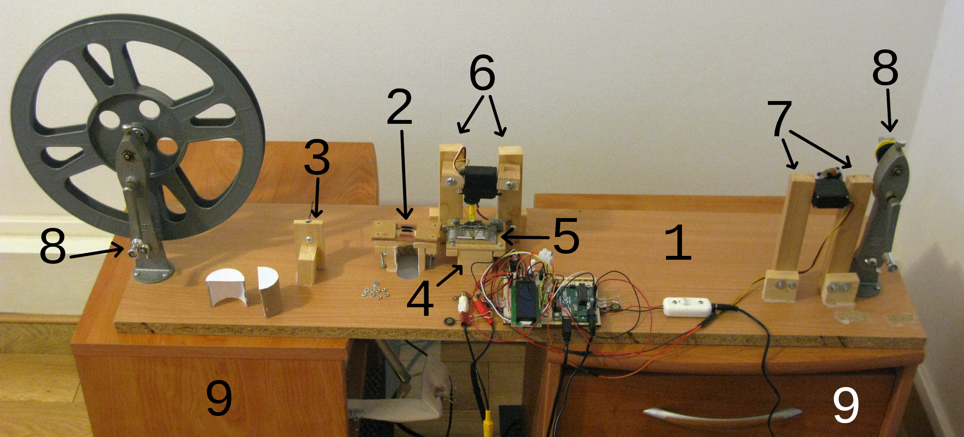
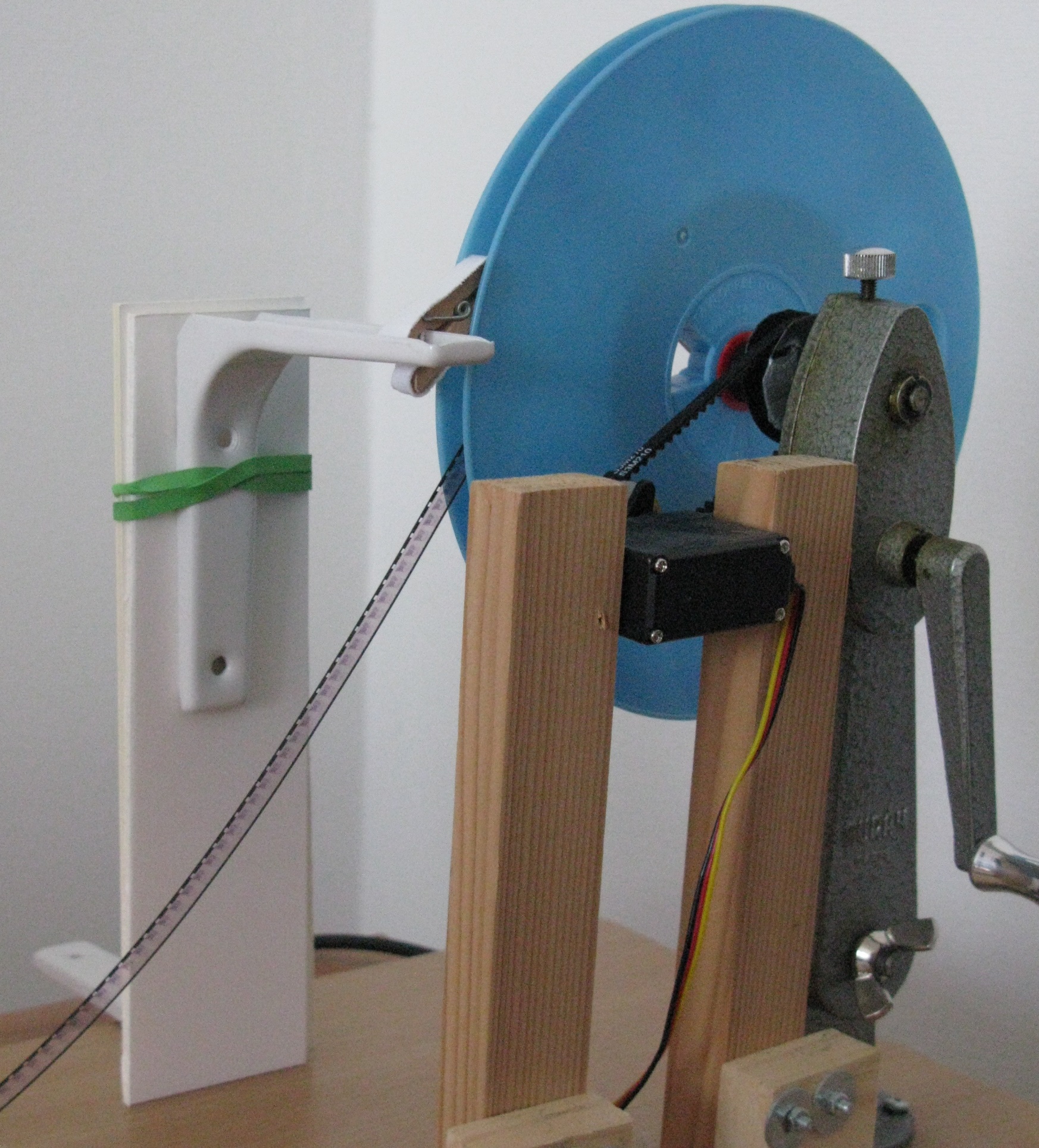
To start with, here is a presentation of the machine that I called FFD-16:
Little tip for this whole page: if you want to enlarge a photo, right click on it and display it in a new tab or download it.
Please note that I am French and that my english is far from perfect. Therefore, some specific terms may be misused in the following paragraphs. If you notice inaccuracies or mistakes, please contact me so I can fix them. Thank you.
Summary
- The budget
- The structure and the mechanical part
- The camera and its accessories
- Lighting
- The Arduino and the electronic part
- The power supply
- How to use it
- What about the other film formats?
- Credits and links
- Licence
The budget
Since this is the major decision criterion before embarking on this project, let's immediately address the question of the budget you will need for the construction of the telecine.
The following table summarizes all the essential parts you will need to acquire, their price, their (very) approximate used price and recommendations of stores where to find them (in France mostly because I live there). For used items, eBay may help you. When a product cannot be found as new or cannot be found second-hand, the same price appears in both columns.
I sometimes refer to very precise models. These are the ones that I use and that give me complete satisfaction. You can, however, look to other models if you already have something equivalent or if you think you can find better or cheaper. However, I recommend you read this entire guide carefully to make sure that your model is also suitable for the very precise requirements of the FFD-16.
I am not affiliated in any way with any of the stores and businesses listed in the table.
If a link no longer works, please let me know by email. While waiting for me to fix it, you can try browsing the Internet Archives to see if a capture is available: Wayback Machine.
| Elements | Detailed description | Where to buy | Price new (euros) | Price second-hand (euros) |
|---|---|---|---|---|
| Structure and mechanical part | ||||
| Chipboard or wood board 100 x 26 x 1,8 cm |
Color doesn't matter, chose one you like The dimensions indicated are the minimum values, except for the thickness which must be equal to 18 mm. If you have a bigger board, it will be bulkier but it will be fine. |
Hardware store | 10 | 1 |
| Wood | 1,8 x 2,7 cm
and 3,7 x 0,9 cm Example |
Hardware store | 10 | 1 |
| MDF 3 mm thick | MDF = Medium Density Fiberboard Example |
Hardware store | 10 | 1 |
| 2 identical bedside cabinets at least 41 cm high with top drawer | They should be perfectly identical, sturdy and have a drawer at the top. | Furniture store | 2 x 33 | 2 x 10 |
| 2 identical indoor doormats | If you don't have carpeting, you'll need to invest in two non-slip indoor doormats to stabilize the bedside tables and dampen vibrations. Of course, they have to be wide enough so that the bedside cabinets can rest on them with at least an inch or two at the sides. Example |
Hardware store | 2 x 16 | 2 x 16 |
| Tools | Various tools you will need to work with wood and assemble the various elements: small wood saw, various screwdrivers, sanding block and its abrasive sheets, round wood file, gimlets and, if possible but we can do without them, a drill. | Hardware store | 40 | 10 |
| Various hardware | You will need the following accessories: screws, nuts, bolts, washers, a 7 mm screw wall plug (not sure of the term), wood glue, superglue, UHU liquid glue (3 in 1 for example) and patafix (= Blu-tack). | Hardware store and DIY store | 20 | 1 |
| Plastic thing | This thing. | Hardware store | 4 | 4 |
| Toothed belts | The size will depend on the dimensions of your device (see below). Example |
Robotics store | 9 | 9 |
| 2mm foam sheet | Example | DIY store | 1 | 1 |
| Protections | Goggles and dust masks | Hardware store | 15 | 15 |
| 16mm movie camera | I used this model. | eBay | 40 | 40 |
| A few meters of leader tape | Specialized shop | 10 | 5 | |
| Rewinder | For this project, I managed to find a Muray 8mm, super 8 and 16mm tri-film rewinder. Any pair of 16mm rewinders will do. It may be possible to make it yourself, but I chose an easier solution. | eBay | 70 | 70 |
| Empty 16mm reel | Diameter should be greater than or equal to that of the largest reel you need to scan. | Specialized shop | 20 | 5 |
| Microfiber optics cloths | Opticians give them away if you ask them nicely. Be careful, you need simple microfiber cloths, not wet wipes. | Friendly optician | 0 | 0 |
| Small things | You will need 6 tight hairpins, a board of glass or other very rigid material, a plastic card (matt and dark or you will have to blacken it with acrylic paint or Posca), a cardboard tube, thin cardboard, an IKEA joining screw (100644) and its complementary screw (100402) and a little bit of white acrylic paint. | At home or at a friend's | 0 | 0 |
| Camera and accessories | ||||
| Sony Alpha 6300 or other mirrorless interchangeable-lens camera with electronic shutter and compatible with a shutter release cable. | Official page | Photo store | 1000 | 450 |
| Sony ACPW20 AC Adapter | Official page | Photo store | 100 | 50 |
| Laowa 65mm F2.8 2x | Official page | Photo store | 500 | 400 |
| SD card class U3 | Photo store | 30 | 20 | |
| Micro USB (B) – RCA (Sony VMC 15MR2) cable | Official page | Photo store | 27 | 13 |
| Tripod with versatile adjustable central column | BENRO tripods are perfect Official page | Photo store | 130 | 90 |
| Tripod ballhead – Kiwi KWBH-2 | Presentation | Photo store | 30 | 20 |
| Sensor cleaning kit | Example | Photo store | 25 | 25 |
| Air blower | Example | Photo store | 10 | 5 |
| Micro HDMI to HDMI cable, compatible with your camera | For the Sony a6300, it is a type D like this one. | Specialized store | 6 | 4 |
| A 1080p screen | A computer monitor or a television with an HDMI port that will help with focusing. A 19 or 23 inch screen will be more than enough. | Appliances store | 100 | 30 |
| Lighting | ||||
| Godox LED 64 | Official page | digit-photo.com | 24 | 24 |
| Mini tripod | Very stable. Example | Photo store | 18 | 10 |
| Polycarbonate 3mm thick – backlight / You can also use baking paper | Example | See link. For baking paper: supermarket | 15 (polycarbonate) | 2 (papier cuisson) |
| Arduino and the electronic part | ||||
| Official Arduino starter kit | You can also buy the Arduino Uno and the electronic components separately but the big advantage of this kit is that it contains a large part of the components you will need and a book which will allow you to learn Arduino programming very easily and which will serve as a reference to identify the components and use them correctly. Official page |
Arduino official store | 80 | 80 |
| Infrared sensor | Example | Electronics store | 9 | 9 |
| JST cable for the sensor | Example | Electronics store | 2 | 2 |
| Continuous rotation Servo feedback parallax | Official page | Electronics store | 30 | 30 |
| Continuous rotation Servo HSR1425CR | Official page | Electronics store | 22 | 22 |
| Additional servo horns | Example | Electronics store | 4 | 4 |
| 2 female RCA plugs | Example | Electronics store | 2 | 2 |
| Cables | Example | Electronics store | 13 | 13 |
| Jumper wires M/M and M/F | Examples | Electronics store | 13 | 13 |
| Tools | Wire stripper, flat pliers | Hardware store | 18 | 18 |
| Soldering kit | Example | Electronics store | 14 | 10 |
| Third hand | Example | Electronics store | 8 | 5 |
| Electric cables and power supply | ||||
| DC power supply unit for the Arduino: 9V and minimum 300 mA | Example | Electronics store | 10 | 10 |
| DC power supply unit for the servos: 6V and minimum 2 A | Example | Electronics store | 16 | 16 |
| DC power supply unit for LED (5v, min. 5 W, with connector 5.5 mm 2.5 mm if you use the Godox LED) | Example | Electronics store | 18 | 18 |
| Low voltage female connector 5.50 mm 2.10 mm | Example | Electronics store | 1 | 1 |
| Switch | Example | Hardware store | 3 | 3 |
| 6-way power strip with switch | Supermarket | 5 | 5 | |
| Total | 2640 euros | 1619 euros | ||
If you borrow equipment or already have a suitable camera or lens (see below), you can save even more on these estimates.
I highly recommend that you invest in official accessories, especially when it comes to the AC adapter for the camera. Considering the price of the device, it would be a shame to damage it with a bad power supply.
The structure and the mechanical part
- General support
- Film gate
- Limiter
- The base of the scrolling mechanism
- Scroll mechanism
- Support of the scrolling servomotor
- Support of the rewinding servomotor
- Rewinders
- Bedside cabinets
For the dimensions, do not rely on the pictures but rather on the following indications because if I had to do it again, I would do it again as explained below.
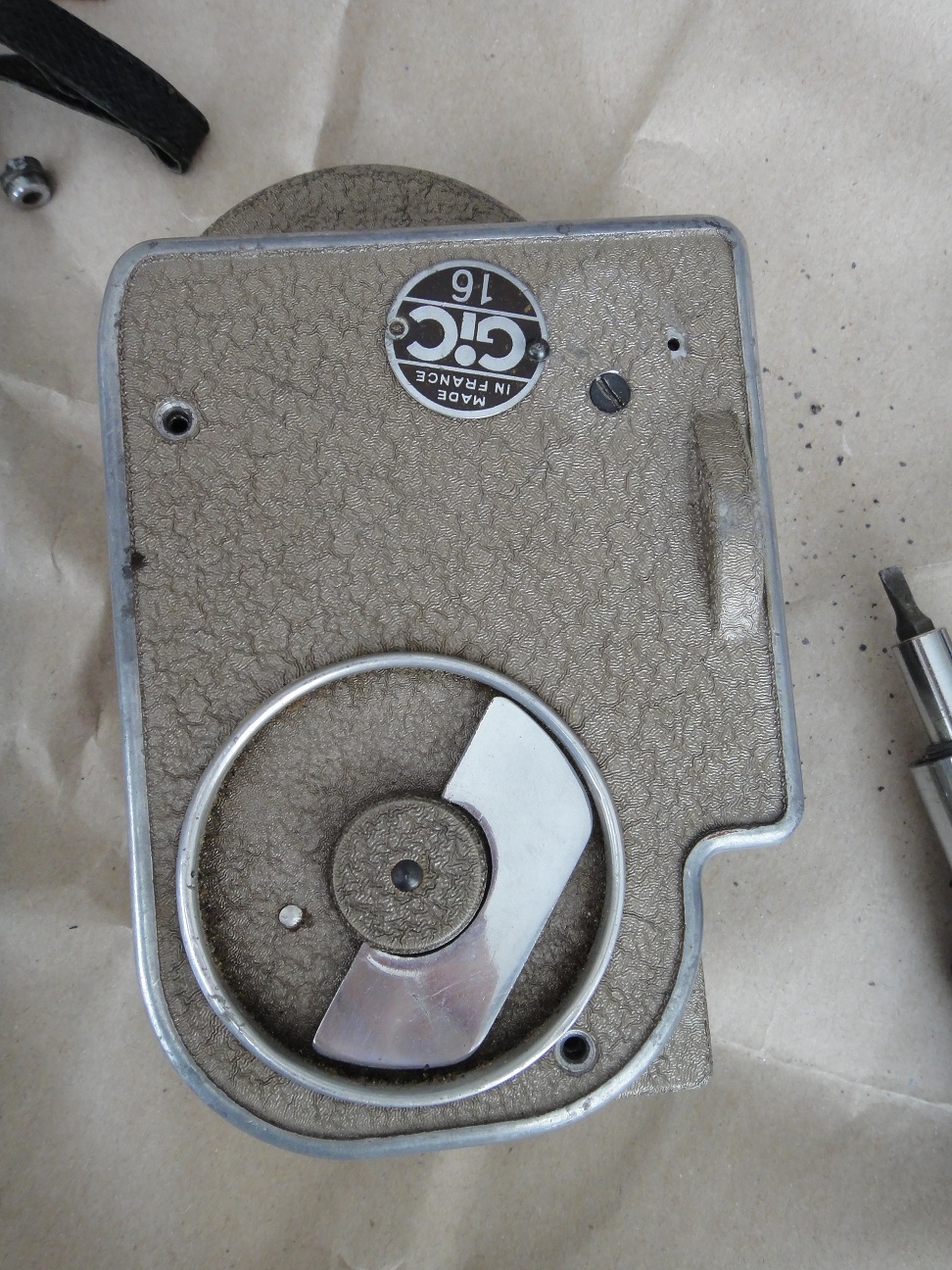
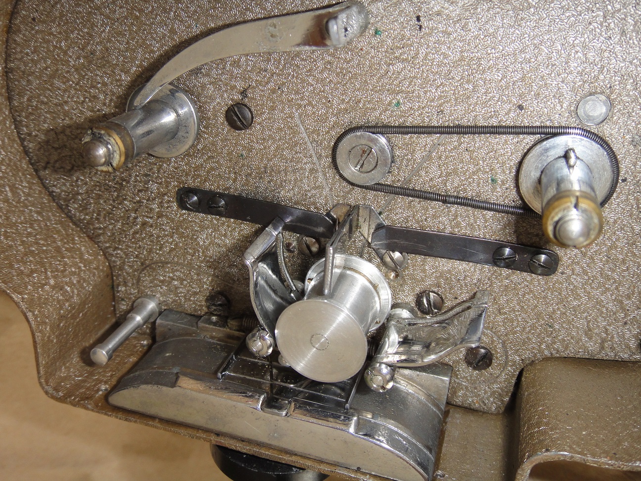
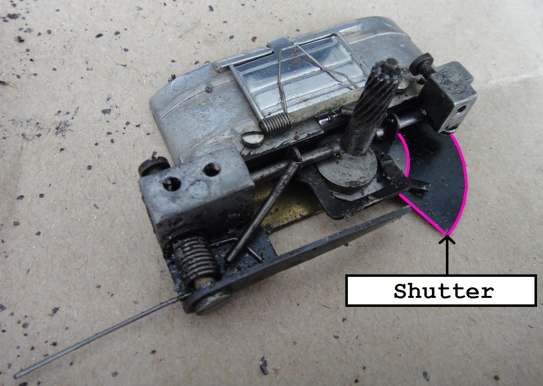
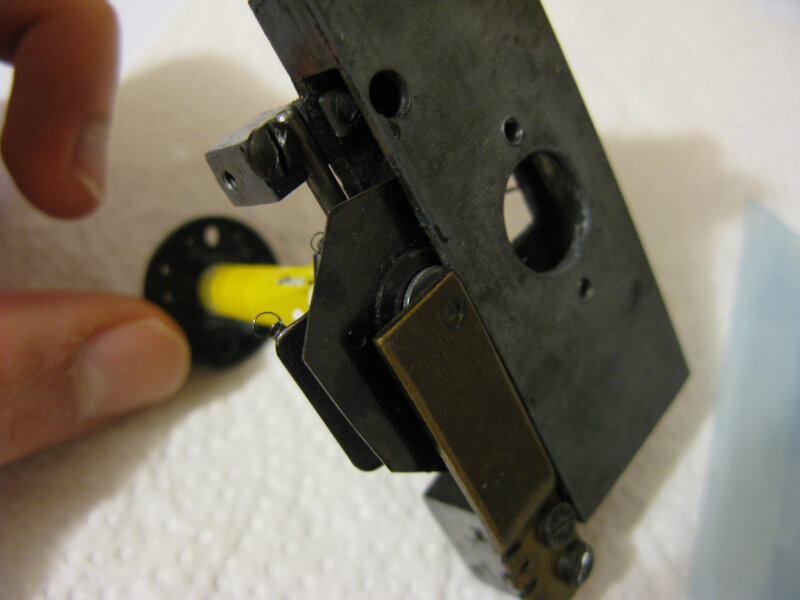
Let's start by disassembling the film camera to extract the scrolling mechanism. The parts will probably be covered with a black grease so wear gloves (see following photos). Thoroughly clean the scrolling mechanism you pulled out of the camera and be careful not to cut yourself as some parts, like the shutter, are sharp. Cut out the shutter so it doesn't get in your way, and again be very careful not to cut yourself with the edges.
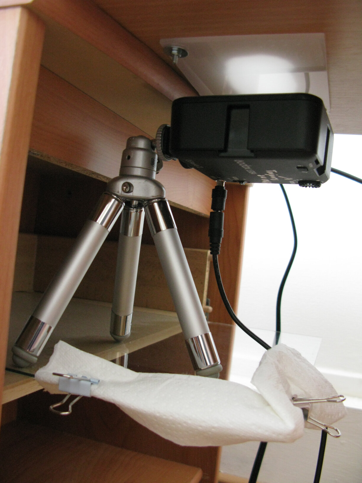
Now let's take care of the bedside cabinets. If they are a bit rickety, take them apart and use wood glue to permanently secure all the joints. If these pieces of furniture are made of chipboard, there will be a coating that will have to be scraped off (with a wide gimlet for example) because the glue only adheres to the wood, not to the coating. The drawer of one of the two cabinets will serve as a support for the LED light placed on its tripod. Be careful, you will not be able to pull out the drawer to place the LED in it as this will interfere with the camera tripod. You will therefore need to use a support which will rest in the drawer from which you have removed the front, which means the support will protrude from the drawer. I personally used a glass plate which has the advantage of being thin and strudy. To prevent the LED from tipping this plate, place a counterweight on the back extremity of the plate. Ideally, the LED should be one inch from the general support. You will therefore probably need to change the height of the drawer. Take advantage of having disassembled the furniture to make this adjustment. Remember to take the plate thickness (glass or wood) into account in your calculation. In the following photo, the paper towel is there to protect the camera tripod from impacts and frictions against the glass.
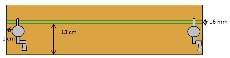
Now let's tackle the general support and place the rewinders on the shelf. It is probably possible to build your own rewinders but I preferred to use those from a Muray tri-film winder (8mm, super 8 and 16mm). Depending on the setting, they allow you to slowly or quickly rewind the film or to let the film run independently of the crank, which is essential for our project because when the film is unrolling or rewinding, we do not want the cranks to rise and fall as the reel rotates. Screw them to the ends of the shelf, leaving a space of 1 cm between the edge of their base and the edge of the shelf. The rewinders must point in the same direction. For the distance to the longest side, have the film follow an axis parallel to the long edge of the general support, located 13 cm from the edge. When you have the rewinders handles on your side, the left rewinder is the input and the right one is the output. The input reels the film and the output rewinds it.
Once the rewinders are fixed, install the reels on them and set a leader tape between the reels. Then let it settle on the general support without touching it. Mark marks and gently trace the lines that follow the edges of the leader tape from one rewinder to the other, using an HB pencil. You have to be able to erase the marks afterwards. You have just drawn the axis of the film which will serve as a reference for all the other elements. Be careful, use leader tape and not film because the film can warp and contract over time. The leader tape will therefore be much more reliable than the film.
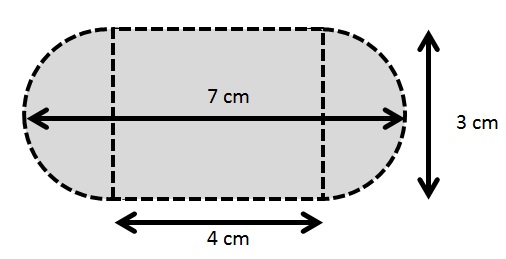
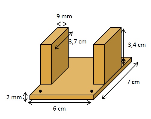
It's time to drill the hole that will let light through the film gate. Its center is located 33 cm from the center of the foot of the input rewinder, and obviously equidistant from the two lines you have drawn. If you have a drill that allows you to make large circular holes, drill a hole 3 cm in diameter and enlarge it with a file. Otherwise, be prepared to struggle with the gimlets and lime. Here are its dimensions:
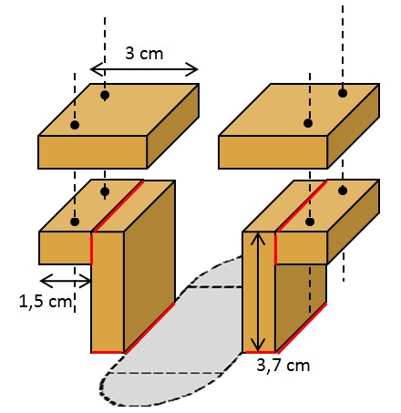
Now let's build the film gate. Cut 6 pieces of the 3,7 x 0,9 cm wood: two of 1.5 cm, two of 3 cm and two of 3.7 cm. On the latter, mark the lateral sides of the batten which are straight and the perpendicular sides that you have cut out. Assemble everything as follows, the red faces are the ones that must be glued together:
Try to center as much as possible along the film axis. If necessary, install leader tape between the two reels to make sure it falls in the right place. Take care to place the smooth and regular faces (so not the ones you cut but the lateral sides of the wood pieces) against the shelf so that everything is as straight as possible. Scrape the coating of the general support a little beforehand (with a gimlet for example) so that the wood glue holds well. The holes should be placed 6mm from the edges so that they are roughly centered on the foam strips that we will be placed later. The screws that will go through the holes are 3mm in diameter and 3cm long. As you drill the holes, the wood may split. Use the thinnest twist to pierce them before moving on to the 3mm gimlet and proceed very gently, backing up every now and then. If it breaks, patch it up with wood glue.
Paint the faces facing the hole white. The light will thus be better reflected on these surfaces.
The wood pieces in suspension in the previous diagram should be extruded a little to leave room for the microfiber cloths. Remove a little material by sanding to obtain a result similar to the following photo.
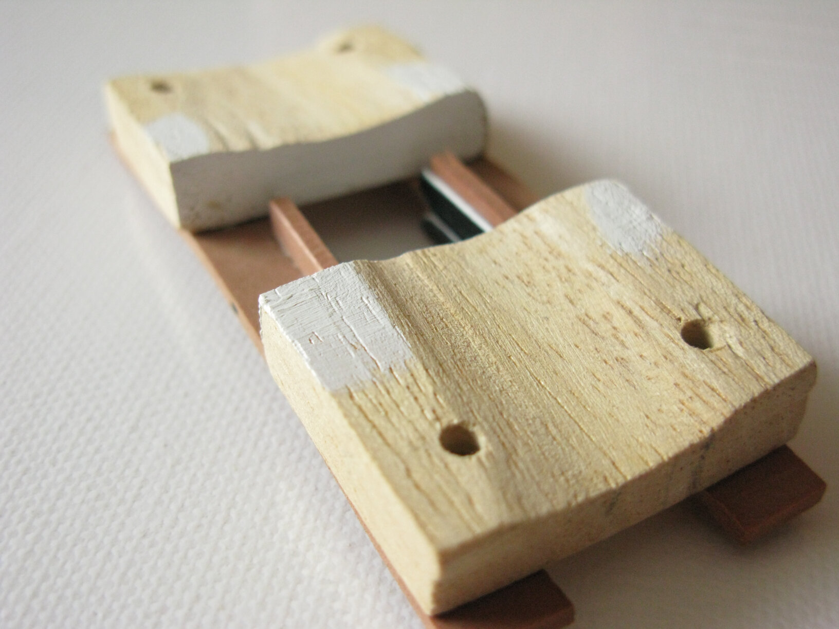
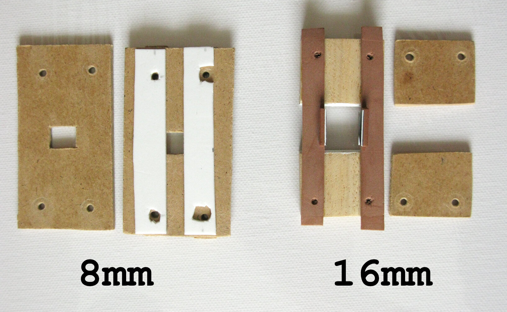
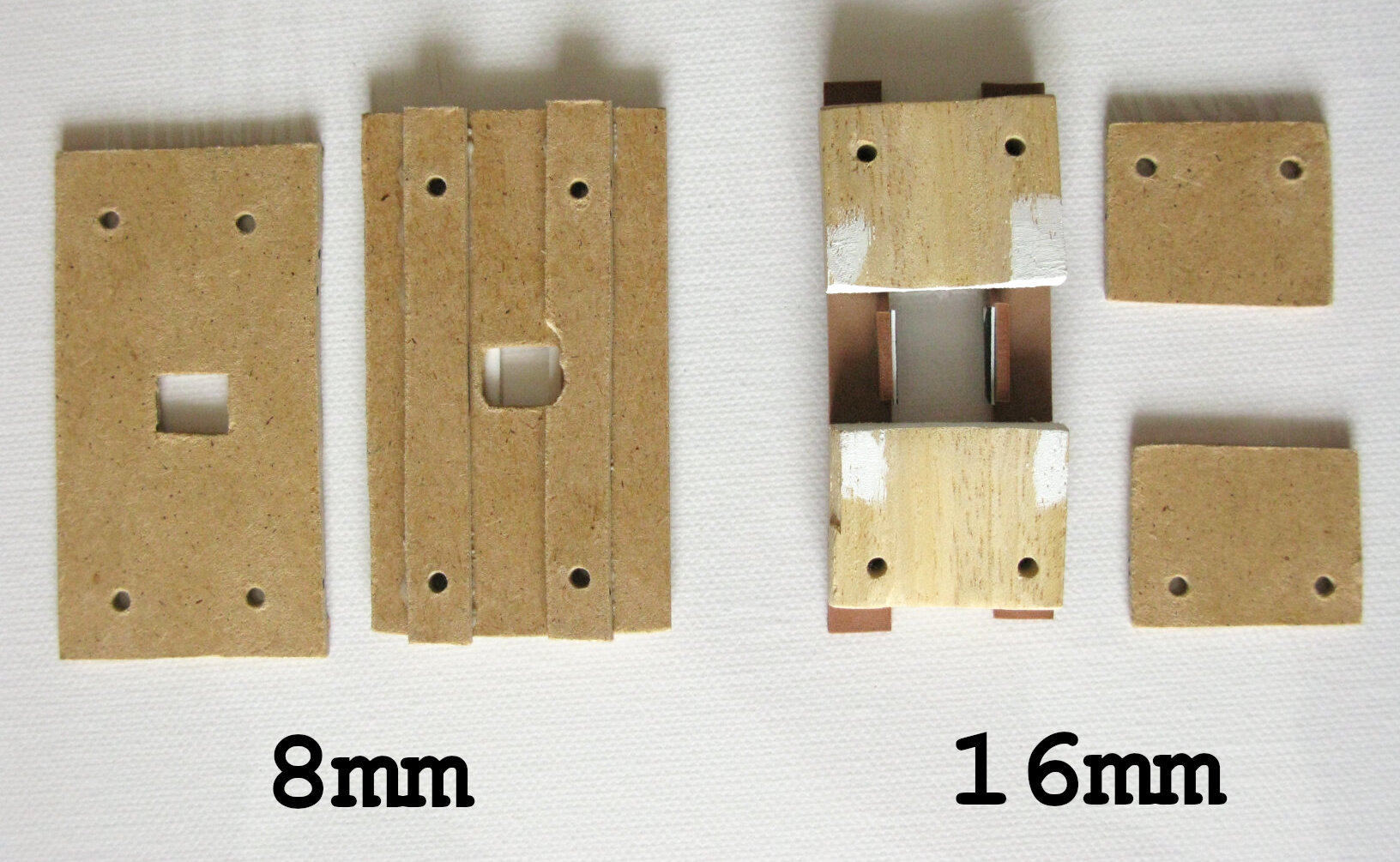
NB: The previous picture corresponds to the removable part of the film gate. When I adapted the system for 8mm film, I used another method to build this part. It's up to you to decide which one you prefer but if I had to do it again, I would also only use MDF cut with a cutter for the 16mm system:
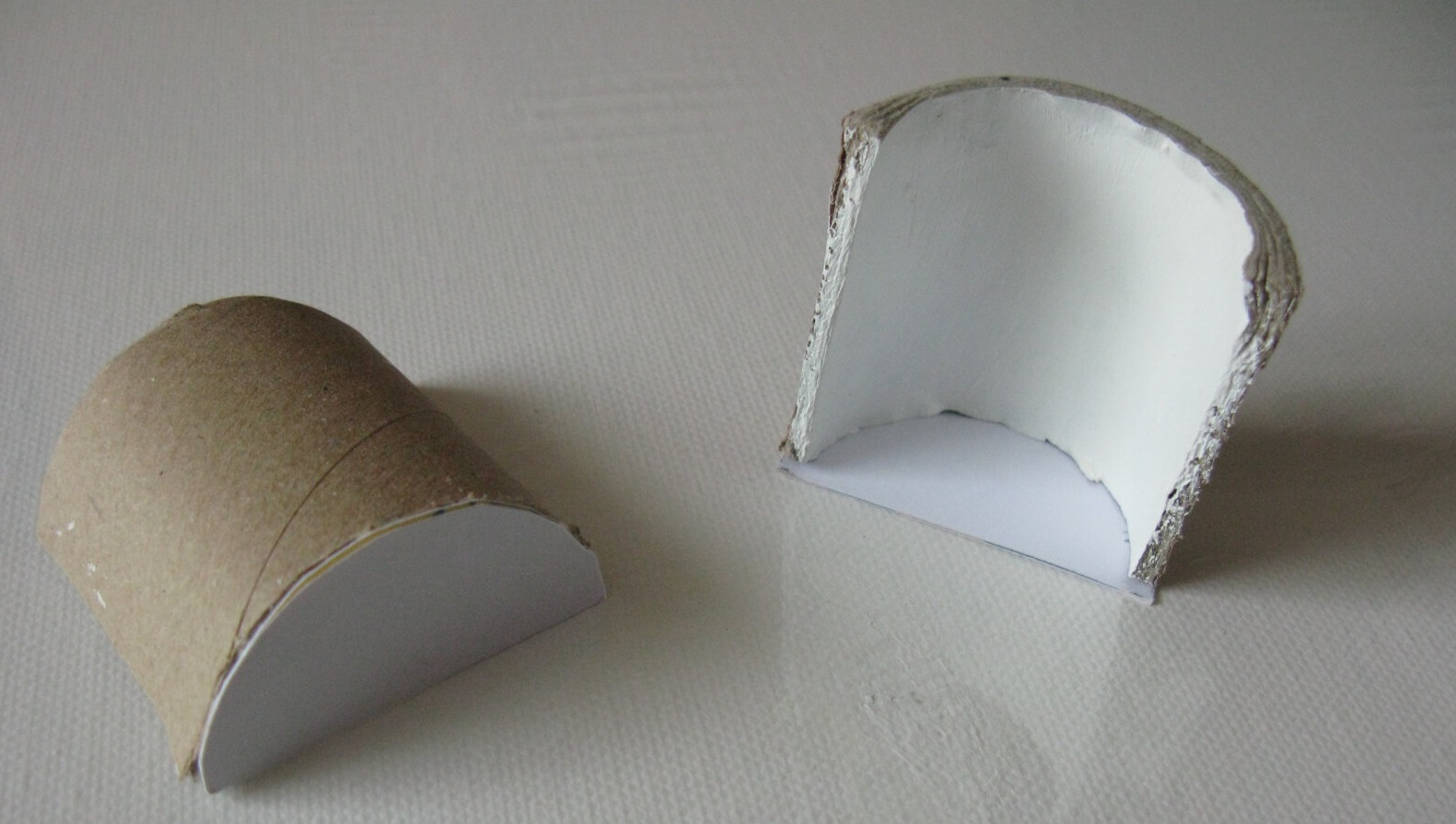
Make caches with a cardboard tube and thick white paper as in the following picture. They will be very useful to hide the powerful light source and thus prevent you from losing your sight prematurely. I also painted the inside of the cardboard white so that the light is better reflected.
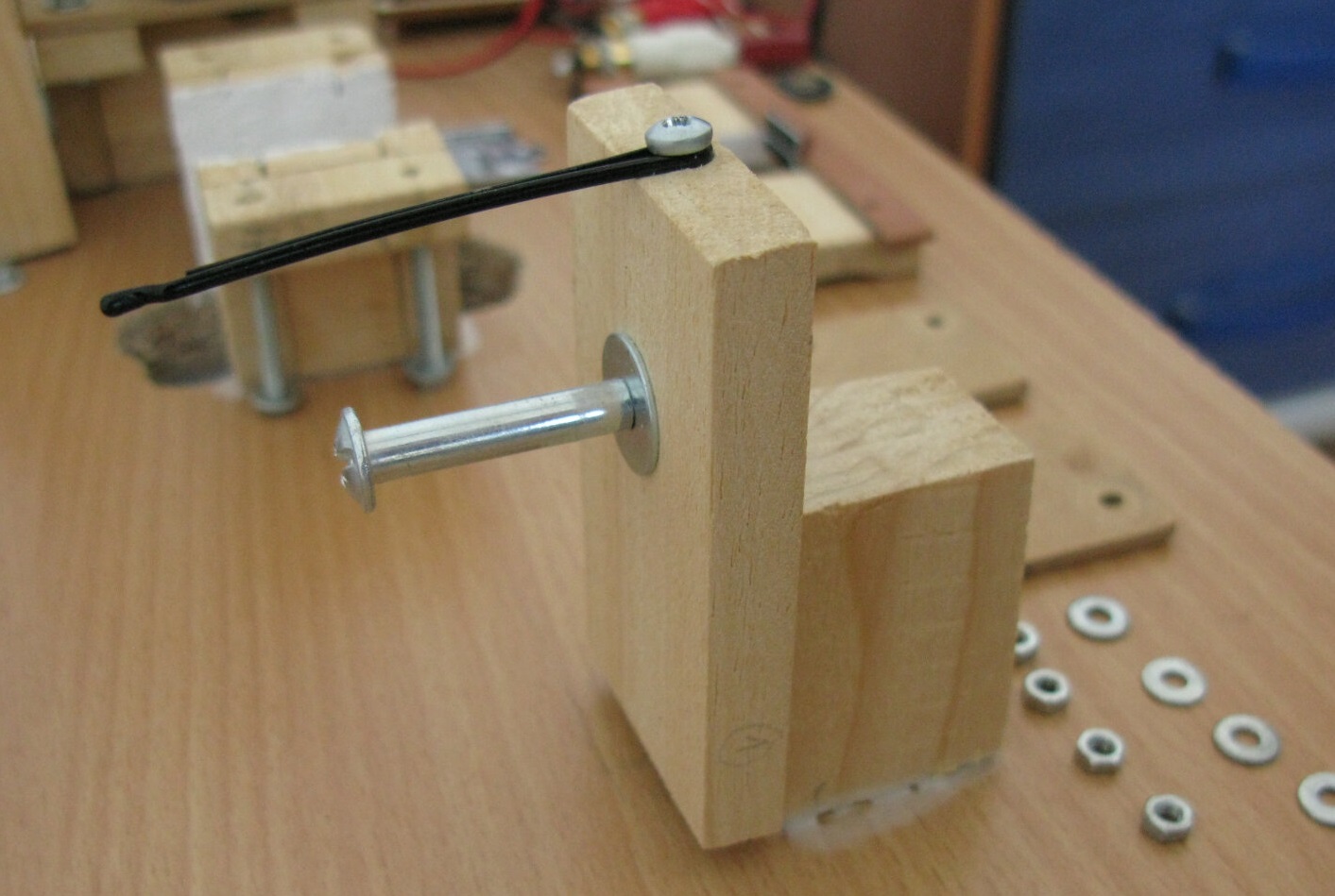
Starting from the middle of the base of the input rewinder, count 21 cm and place the "limiter" element, which places the film at the correct level before it goes in the film gate. This element consists of a 7.5 cm long 3,7 x 0,9 cm wood piece, a 4 cm long 1,8 x 2,7 cm wood piece, and a joining screw, without forgetting a washer. Assemble the pieces of wood with wood glue, drill a hole with the appropriate gimlet so that once placed in, the bottom of the joining screw is at the height of the film gate (at 4.7 cm in my case), and attach a hairpin aligned above the joining screw, as in the following photo. Then glue everything on the general support (don't forget to scrape the coating).
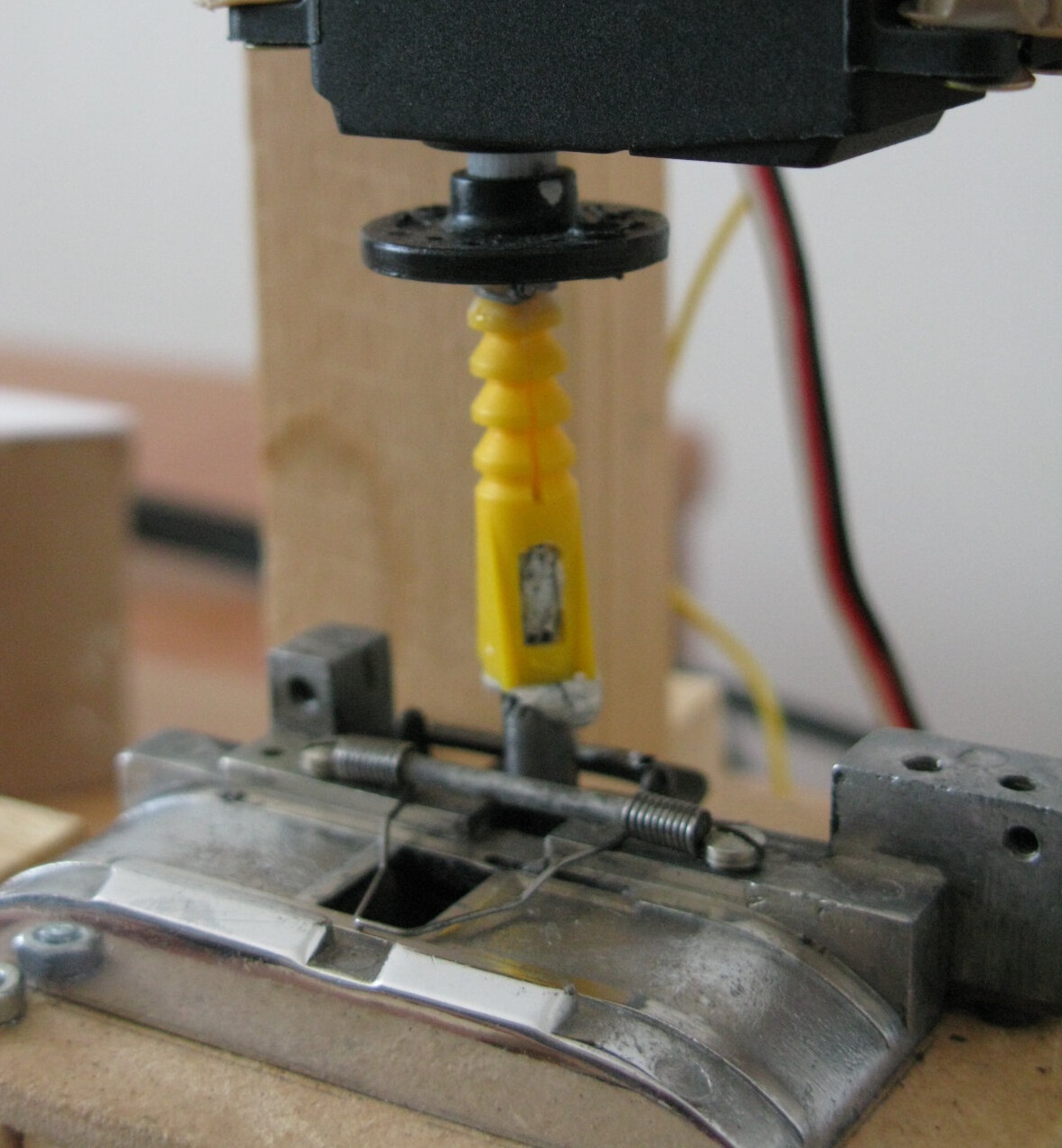
Now let's move on to the support of the scrolling mechanism. In the photos, you will see that I did not follow the explanations below so beware of the photos. In the thin wood pieces (0.9 mm thick), cut two pieces of 3.4 cm (by 3.7 cm) and cut two pieces of MDF 6 cm by 7 cm. Glue three pieces together as follows:
The second piece of MDF serves as a support for the scrolling mechanism. If you have opted for the same film camera as me, you will see two holes under this mechanism that you can use to fix it on this second piece of MDF using small suitable screws. Take the time to unscrew the golden piece held by 2 screws to add a small washer as in the following photo, and a little lubricant. If you don't, the spinner will eventually punch a hole in the MDF that supports the mechanism and the hook will no longer rise high enough to pull the film (it happened to me). Check that the golden piece is as far to the right as possible (in the folowing picture it would rather be at the bottom) and that the claw comes out without problem on the left and falls back to the right without hitting the edge when you turn the rod clockwise. Finally assemble the two pieces of MDF by drilling holes at the 4 corners and passing bolts.
To secure the support of the mechanisme to the general support in the correct position, run leader between the two reels and wedge it in the scrolling mechanism. Try to align all of this as best as possible, taking the film axis and the center of the film gate as a reference. Also make sure that the photogram is centered on the window. To do this, manually scroll the leader by turning the rod of the mechanism clockwise until it is in position (the mechanism operates in two stages: scroll - position).
Now comes the trickiest part. From your foam sheet, cut two strips 1 cm wide and 8 cm long. Take care to cut them along the edges of the sheet, which are more even than your cut with the scissors. Identify the two sides, for example by marking the cut side with a marker point, in order to subsequently place the original regular side on the film side. Install leader between the input reel and the output reel and wedge it in the gate of the scrolling mechanism. Scroll the leader by turning the mechanism rod until it is in position. Rest the leader on the film gate, the floating parts of which are held by screws which heads are at the bottom (so that they do not get in the way at the top). Apply a few drops of UHU liquid glue (not superglue because it dries too quickly) and gently place the strips of foam on either side of the leader, in lateral contact with it, without moving it at all. With UHU liquid glue, you have a little time to position the bands correctly before complete drying, so take the opportunity to adjust the position. If you notice after the glue dries that there is too much or too little space between the foam strips, do not hesitate to tear everything off, sand down the traces of the foam stuck on the wood and start over. Personally, I had to do it twice before I was satisfied (but I had used superglue).
Cut 6 strips of microfiber cloth 16 mm wide and a minimum of 11 cm long, and a 7th of the same width but at least 13 cm long, and wash them with Marseille soap and rince with water. Make a notch in the longer strip so that you can let the scrolling claw do its job. Cut out yet another piece of 14 mm wide and 10 cm long. It will go on the upper part of the scrolling mechanism and thus let the claw pass by without damaging it. You will need one last strip for the upper limit. It will be held by the hairpin and will protect the film from friction against the joining screw.
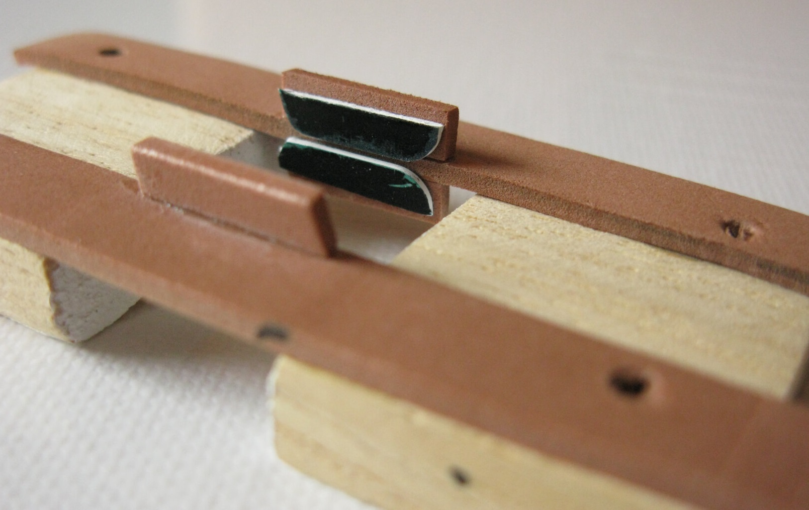
The next step is optional but may be necessary if you are scanning slightly distorted film. It consists of installing guides for the film on the foam strips so that it lies flat. Start by cutting small pieces of foam not exceeding in length the opening of the film gate (microfiber strips included) and glue them as in the following photo. Then cut four pieces of plastic card with the rounded edge towards the entry and file the other end a little to round it off to avoid scratching the film on contact. If the surface of the card is too light, paint it black so that it does not reflect light back to the film. Place some leader in the film gate and secure it as if you were going to scan it (with screws, nuts and microfiber strips). Using tweezers, glue the pieces of plastic along the primer with liquid UHU glue. Use as little glue as possible to avoid drippings that will stick to the primer.
Cut two pieces of MDF the same size as the floating pieces and drill holes in them at the same locations. Place them on top of the foam and drill the foam following the holes.
Your device should then look like this:

The next step is to place the supports for the servomotors. For this step, I do not have any measurements to give you because it is mainly a question of placing them so that the servomotors are kept in the correct position. Here are some pictures to give you ideas.
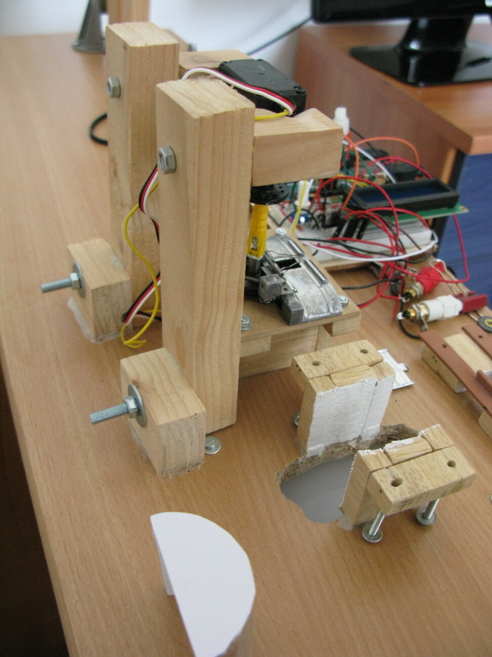
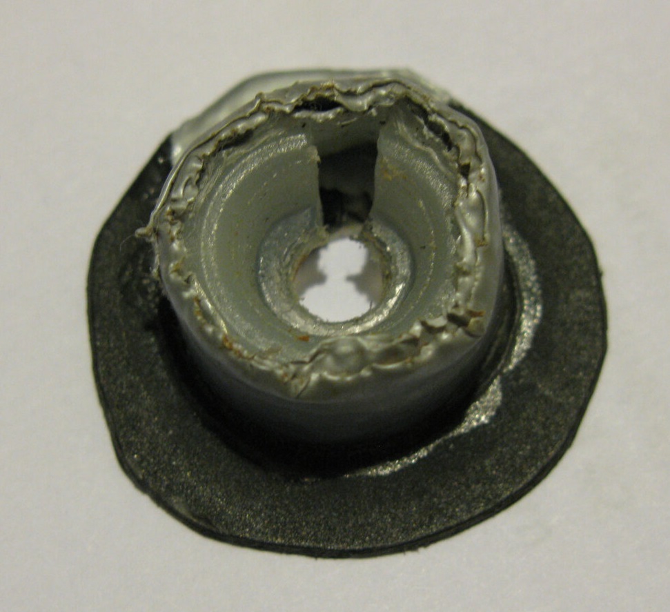
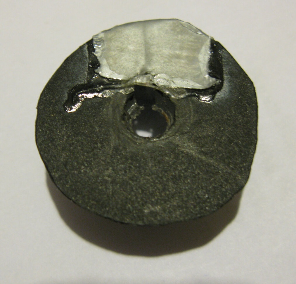
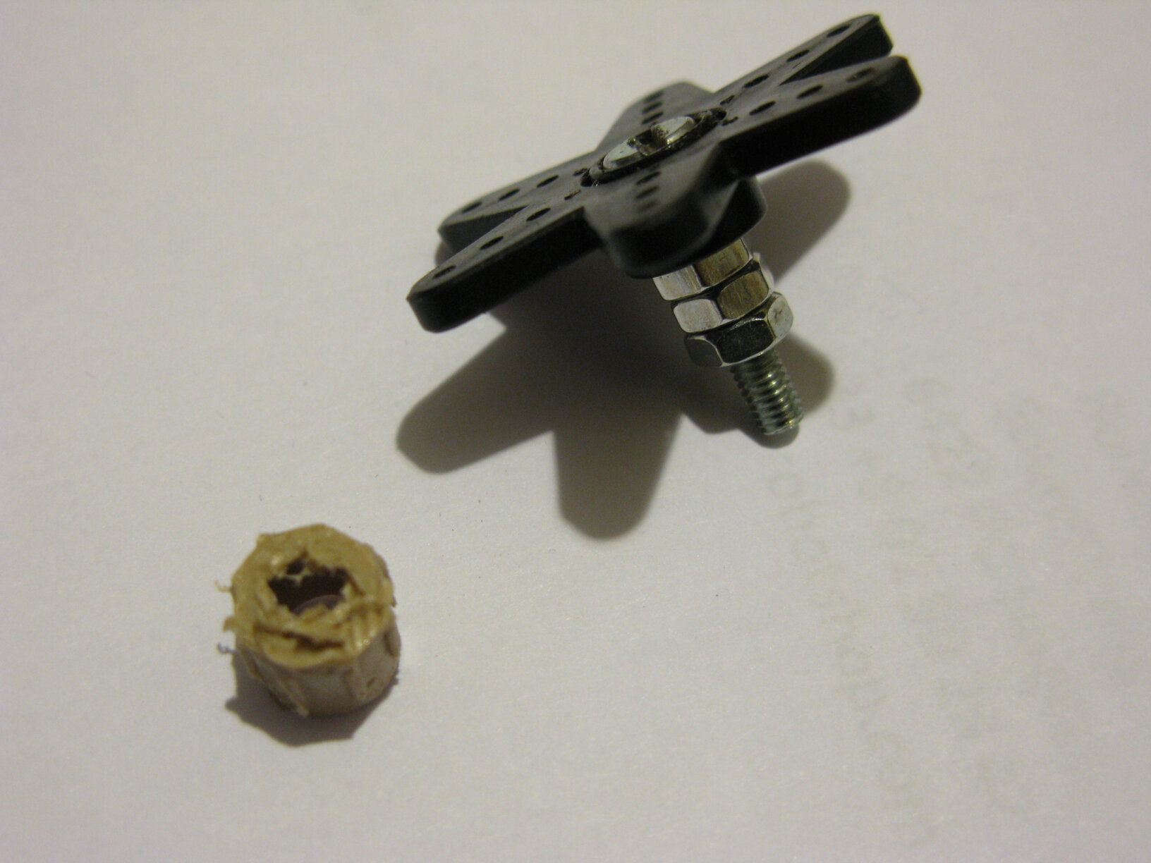
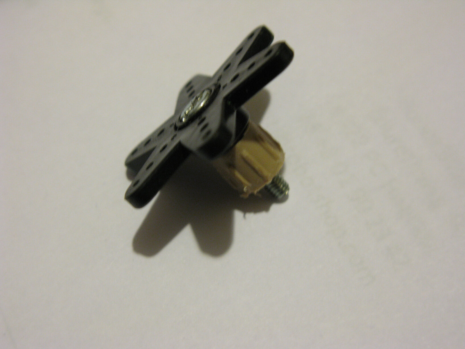
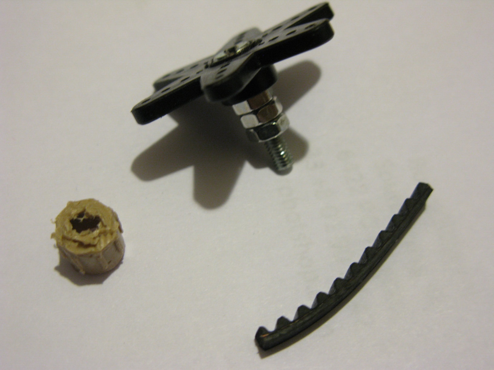
Finally, here's how to adjust the rewind media. Since the minimum speed of the rewind servomotor is still too high, we must find a way to reduce the rotation speed of the reel. For this, we will use a round plastic end cap that we will notch so that it can pass around the axis on which we mount the reel (see next photo). As this is still not enough, add a few turns of tape until you get a diameter of about 1.8 cm.
Then apply a toothed belt on the device you obtained (see following photo). Cut a section of belt the length necessary to cover the entire turn (mathematical reminder: the perimeter is 3.14 x the diameter). I recommend that you start by gluing one end of the end of the belt, wait for it to dry, then tighten the belt well, glue it as you go and cut only at the end so that it is well stretched and the correct size. To prevent the belt that will later be set between the servo and the rewinger from slipping, add a plastic disc about 3 cm in diameter.
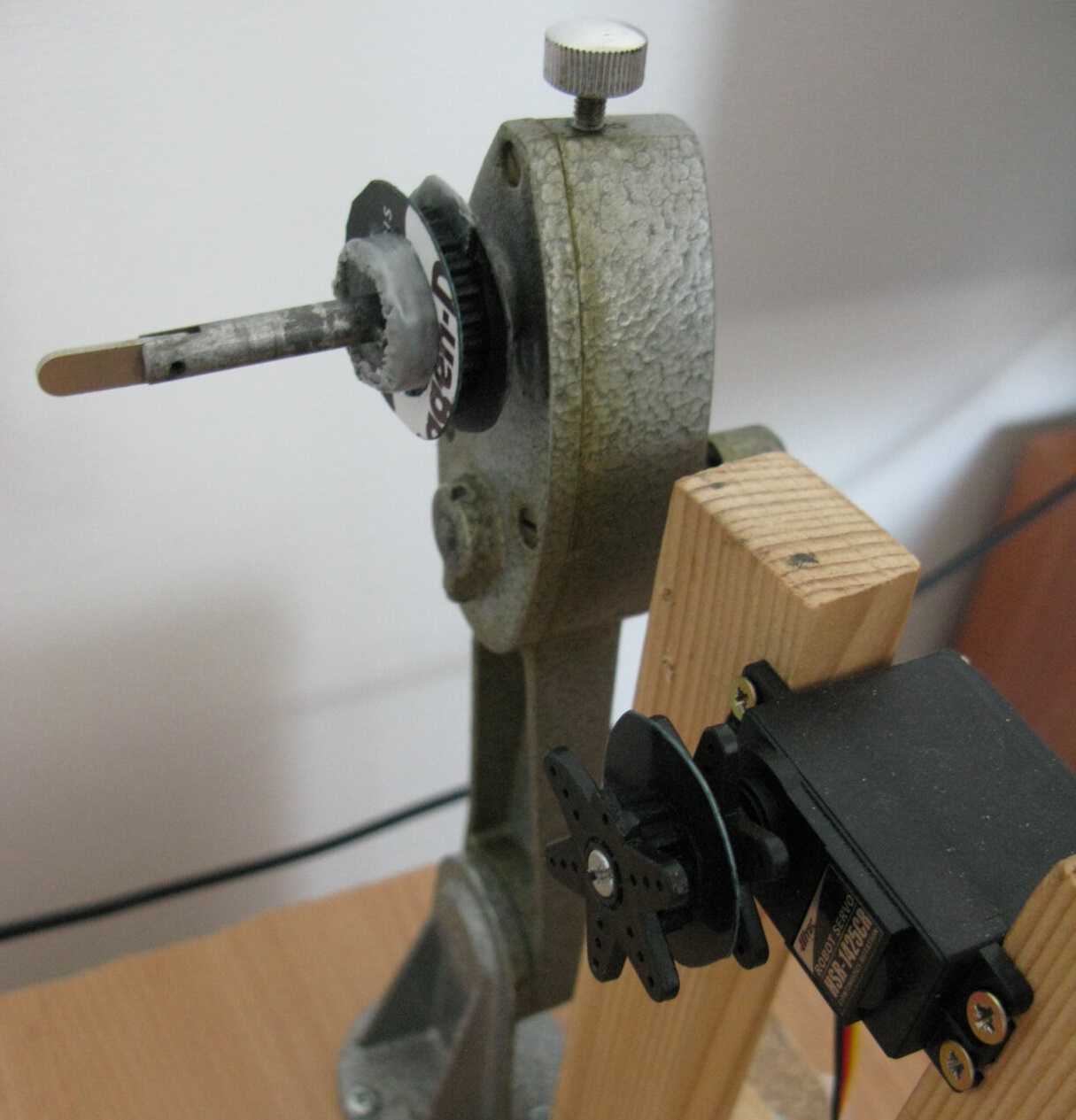
I will present the servomotors in a following section, but I will already explain here how to prepare them. For the rewind servomotor, this is pretty straightforward. Use two servo horns, a plastic disc, a large screw and nuts, as in the following photos. I added a plastic cap to "thicken" the nuts. Also glue a piece of belt on it to obtain a toothed wheel 1.7 cm in diameter. If the diameter is too small, the drive belt will jump. Personally, I glued an additional strap of toothed belt on top of the previous one to get the right diameter. (see the result on the previous photo, where you will notice that I accidentally broke a wing of a servo horn)
Warning: the drive belt must be tight during scanning and it is not elastic. Therefore, you should be able to easily tilt the rewinder so that the belt can be put on and off before and after each scan (see the "How to use" video at the end).
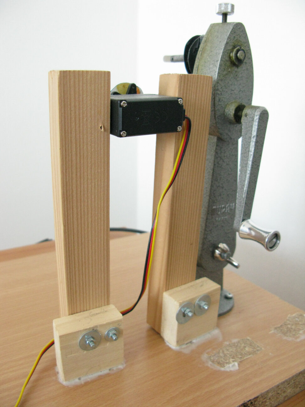
For the scroll servomotor, use a 7 mm screw wall plug that you will fix to a servo horn with a small screw (head of the screw inside the servo horn) and a wire that you will tighten with flat pliers. Now you just need to thread the rod of the scroll mechanism into the screw plug, adding a little patafix (or blu-tack) to strengthen the connection without it being final. If the film gets stuck, you may break it if the connection is too strong.
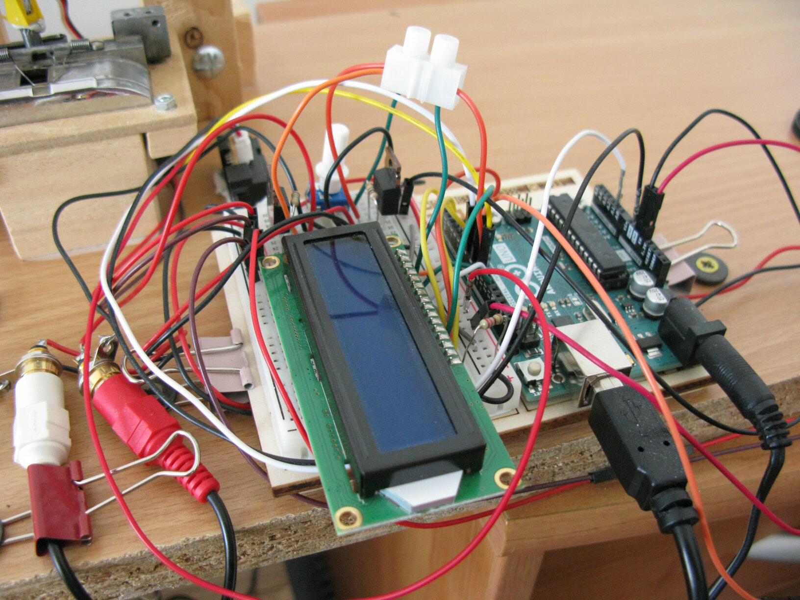
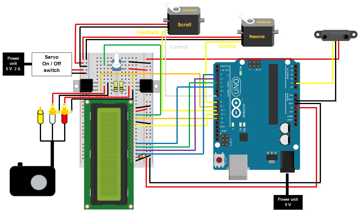
Finally, all you have to do is attach the Arduino and its breadboard as close as possible to the edge, on the crank side. The following picture shows you an example. Leave room for the servo switch which will come in later and which you can place to the right of the Arduino.
The camera and its accessories
The camera
Only mirrorless cameras with electronic shutter mode (also called silent mode) are suitable. So you can forget about compact cameras, bridges and DSLR cameras. Let's see why.
The pictures you want to photograph are very small and you should minimize as much as possible the vibrations that make the camera shake. Hence, you don't want to use a mechanical shutter device. We could then wonder if we could use a camera like the Sony NEX-3N which relies on an electronic front-curtain shutter (EFCS). Of course, the vibrations are very reduced since the mechanical shutter intervenes only to close. However, there is a second parameter to take into account: the wear of the mechanical shutter. A camera is supposed to be able to take 50 000 to 500 000 shots, or even more depending on the model, which is very respectable for normal use. However, the film scanner involves capturing 24 frames per second of film, which represents 21,600 photographs for a 15-minute film. At this rate, the shutter would die very quickly. I started with a Sony NEX-3N camera and its shutter got stuck after about 15 reels (10 minutes each). Therefore, you absolutely need a mirrorless camera capable with a 100% electronic shutter. Pesronally, I chose the Sony Alpha 6300.
In order to optimize the quality of your shots, I recommend that you inspect the sensor from time to time and clean it if necessary. To find out how, I invite you to watch this video.
I recommend the use of cleaning kits like those from the Visible Dust brand, which are easily found in France and work very well. More details on these products here.
AC adapter
Since a battery will not be enough to keep your device running during a complete scan (consider about 5 hours for a 10 min film shot at 24 fps), you will need to power it from the mains. I recommend using an official AC adapter from your camera brand. For the Alpha 6300, this is the Sony ACPW20. You will not be able to power it through the USB port because it will already be occupied by the trigger cable.
The lens
The Laowa 65mm F2.8 2x is perfect and comes in several models, each compatible with a different brand to keep everyone happy. Magnification between 1x and 2x is required. There are also lenses with a minimum magnification greater than 2x. To shoot 16mm, this will be too much because the image will not fit in the frame.
If you're on a budget, you can also opt for a cheaper macro lens like the Sony E 30mm F3.5 (SEL30M35) macro lens. A very complete test of the latter is available here.
The SD card
You will surely want your scanner to take pictures as quickly as possible. To avoid any problems, buy a U3 class SD card (min. 30 MB/s write speed). I started with a U1 card but at a speed of 48 photos per minute, it saturated after a time varying from 3 min to 50 min. The delay was completely random and unpredictable. With a U3, I can take 60 8MB photos per minute without pausing the camera for 6 hours straight.
To help you choose the right capacity for your memory card, ask yourself what photo quality you want, the size of the pictures you want to capture, and what is the length of your reels and the frame rate of your movies. Make sure an entire film fits on the card, since it will be much more convenient than having to pull out the SD card every hour to transfer the pictures.
Please note that for some reason, Sony cameras can only store 40 000 images on a memory card. However, this is sufficient for an entire day of scanning.
The tripod and the tripod head
You will need a tripod with an adjustable center column so that the camera can overlook the film that is playing. In this category, the Benro brand offers good quality items for a very reasonable price. I personally opted for the TGP17A model.
Please note that these tripods are sold without a ball head. You will need a ball head, if possible with a bubble on the side, as on the Kiwi KWBH-2 model, so that you can point the camera downwards and use the bubble as a reference.
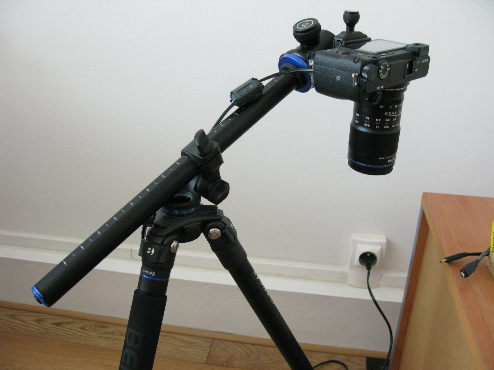
Note: Why not put a camera mount directly on the general support rather than using a tripod?
For several reasons. The first one is that the rotation of the servomotors could cause the device to vibrate and cause slight motion blur. This is probably negligible but better to eliminate the risk. The second reason is that you will have a lot more freedom of movement and positioning with a tripod that is independent from the rest of the structure. The images you want to shoot are tiny, and if you move the camera a little in one direction, the image may go completely out of the frame. It’s hard as hell to adjust the frame by moving the camera around, let alone on a DIY stand that isn’t as convenient as a tripod. Indeed, the frame is made first by placing the camera approximately above the photogram, then precisely by manually moving the general support, as we will see in the "How to use" section.
The trigger cable
In order to be able to trigger the shutter without having to touch the camera release button, you will need to use a cable. For Sony devices with a "multi / micro USB connector" port, you must connect an RCA cable (Sony VMC 15MR2). The red RCA tip is then equivalent to pressing halfway which locks the focus while the white tip is equivalent to the shutter button. Therefore, you just need to short-circuit each tip simultaneously to trigger a shot. The yellow tip is useless here.
Micro HDMI (type D) to HDMI cable
Any cable compatible with your camera will do. The goal is to connect your device to an external HD display.
A 1080p screen
A computer monitor or a television with an HDMI port will help you a great deal in focusing. A 19 or 23 inch screen will be more than enough.
Lighting
The light source
First and foremost, a safety note: the lighting you are going to use is very powerful so be careful with your eyes.
To benefit from perfectly homogeneous lighting, nothing beats the diode panel, also called LED video light. You could use a normal LED bulb or a spotlight, like did many people who have made their scanners. However, tests with these light sources were inconclusive as the light intensity fades away at the edges of the image. In addition, with an AC power supply, glitches may appear in the image, such as horizontal stripes or variations in light intensity.
When using the LED light, remember to set the intensity to maximum. If you do not do this, you will see horizontal lines appear because the diodes flash to reduce their intensity causing the aberrations you can see in the following picture.
The Godox LED 64 torch has the ideal dimensions and can be powered from the mains via a power supply to be purchased separately.
Diffuser
To diffuse the light and make it even more homogeneous, it is necessary to use a diffuser. I recommend a 3mm thick polycarbonate sheet with 40-55% transparency.
You can also use baking paper that you will fold as many times as necessary to properly diffuse the light and that you will place on the LED panel. Do not use normal paper or other flammable materials. The advantage of baking paper is that it can withstand the heat of the LED perfectly.
Be careful, the baking paper must be very even and not have a pattern. Otherwise, you may see it appear in the photos. Experiment by adjusting focus and exposure on the film, then taking a photo without the film to check if the white image is perfectly homogeneous or not.
The LED's tripod
To hold the LED, nothing better than a small, very stable and solid tripod. Avoid tripods with flexible legs. Any model that allows horizontal orientation of the LED panel will do.
The Arduino and the electronic part
Here comes the part where you have to work hard with your brain, unless you trust me completely and plan to use the provided code as is. However, in the event of a malfunction or if you want to add your personal touch, I recommend that you take the time to learn the basics of the Arduino programming. I reassure you, the Arduino language is very accessible and I will even tell you that I took pleasure in learning it and writing the program whereas I normally hate programming.
As shown in the first table, I advise you to buy the official Arduino starter kit because it contains a large part of the components you will need and a book that will allow you to learn Arduino programming very easily with fun exercises and which will serve as a reference to identify the components and help you to use them correctly. This manual has helped me find solutions to many, many problems.
Basis
The Arduino Uno microcontroller, referred to as Arduino in this guide for simplicity, is a marvelous little device that analyzes input electrical signals to perform all kinds of output tasks. Rather than paraphrase, I invite you to consult the official presentation of the Arduino Uno that explains the basis of this microcontroller.
To learn more about Arduino, I invite you to check the dedicated Wikipedia page.
The servomotors
Servomotors are, as their name suggests, motors that do what we ask them. There are two kinds of servos: classic ones, which have a rotation angle limited to 180°, and continuous rotation servomotors, which can rotate 360°. By sending a signal, we can control the position of the former and the speed of the latter. Unfortunately, the position of continuous rotation servos cannot be controlled because, as their name suggests, they rotate continuously. They have 3 cables: two for the power supply and a third for the input signal to control them.
Two continuous rotation servomotors are required for this project. The first will be used to rotate the film scrolling mechanism and the second will be used to rewind the film whenever necessary.
Let's start with the simplest: the rewind servo motor. A simple continuous rotation servomotor will do the trick. Be careful, however, the cheapest may be very noisy. The model I use for rewinding has the advantage of being reasonably quiet (Hitec HSR1425CR).
For scrolling you will need a specific continuous rotation servomotor. The Parallax "feedback 360°" model is the one I use. It has an additional cable: an output that sends a signal allowing its angular position to be known at any time. This will be essential to trigger the shutter when the scroll mechanism is in the right position.
Note: In the early versions of the machine, I used a mechanical trigger system. When the servomotor was spinning, it would press a microswitch once per revolution, which activated the shutter. But this system, in addition to being very noisy, does not work with all cameras, especially with the Sony Alpha 6300. The shutter release button is so sensitive that, even in “single shot” mode, it sometimes took two photos in a row when the microswitch was activated. I think this is due to the fact that the contact inside the microswitch is not perfect and whenever it "vibrates", "bounces" or "jumps" even for a fraction of a second, then 2 photos are taken. So forget about the mechanical triggering systems because the electronic system that I propose is much more reliable, will cause you less headache and above all, it is completely silent.
The infrared (IR) sensor
To trigger film rewind when the film gets too loose on the output side, you need to send a signal to the Arduino that says: "Wake up the rewind servomotor so that it does its job." For this we will use an infrared distance sensor. This sensor will allow to define two conditions: either the film is in front of it, at the bottom, and it is necessary to rewind, or it is high enough and it is not necessary to rewind it.
The IR sensor measures the distance that separates it from the object in front of it and sends the information to the Arduino in the form of a voltage (more precisely it is an analog signal between 0 (0 V) and 1023 ( 5 V), which must therefore be divided by 1024 and multiplied by the supply voltage of the sensor, i.e. 5 V, to obtain the value in volts). The following graph, which comes from the sensor data sheet, allows us to view the signal values sent to the Arduino (in V), depending on the distance from the object (in cm).
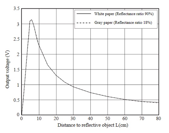
After several tests, I found that the ideal position for the IR sensor was facing the axis of the film, at the foot of the support of the scrolling mechanism and to set a threshold at 1.1 V. If the voltage read is higher at 1.1 V, the distance is between 2 cm and 25 cm, so the film is in front and must be rewound. On the other hand, if it is less than 1.1 V, the distance is either less than 2 cm or more than 25 cm. Since it cannot be less than 2 cm, it is necessarily greater than 25 cm, so there is nothing in front and it must not rewind. You will therefore note that it is crucial not to put anything too close to the sensor otherwise it will rewind constantly. Rest assured, even with a 600 m reel very close to the general support, it is too far from the sensor to trigger it.
Secure it to the general support with pataxif (blu-tack). It is not recommended to fix it permanently as you may need to adjust its position from time to time in the beginning and if you change film format.
MOSFET
The MOSFET is a type of transistor which lets, or not, pass a current between two of its legs, called “source” and “drain”, depending on the voltage sent to its third leg, called “gate”. To summarize simply, they are electronic switches.
Enhancement-mode MOSFET close the circuit between source and drain when current is sent to the gate while depletion-mode MOSFET remain closed until they receive current. However, since we want to close the circuit intermittently and leave it open the rest of the time, we will use enhancement-mode MOSFET.
The type, N or P, indicates in which direction the current flows.
We will therefore use IRF520 models, which are N-type depletion-mode MOSFET. If you only have P-types, you just need to reverse the connections from the assembly diagram shown below.
To ensure that the circuit remains open when asked, you must place a 1 kOhm resistor between the gate and the source (connected directly to ground). Thus, when no signal is sent to the gate, its potential is equal to 0 V.
To learn more about MOSFET, I invite you to consult the dedicated Wikipedia page.
LCD screen
This gadget will be very useful to display the number of pictures taken since the start of the current scan. This will ensure that the number of shots commanded by the Arduino, so the number of frames that have scrolled through the capture window, matches the number of photographs taken by the camera. Otherwise, you will know that the camera has "forgotten" photos or if, on the contrary, an error has caused it to take too many pictures. On several tens of thousands of photos of the same film, we routinely observe a shift of 2 to 4 photos between the two values, which is very negligible. This is probably due to a misstatement of the counter or the sometimes necessary shutdown and restart during scanning which can cause counting errors. Nothing serious, then.
Wiring
Please note that the servomotor control cable may be yellow or white. On the models I use, the Hitec servomotor has a yellow control cable while on the Parallax model it is white and the feedback cable is yellow.
The code
A quick note on the "pause" function. In the code above, I decided to take the camera off for 15 minutes every 10 000 photos. These values are completely arbitrary and you can change them as you feel, or even remove the pause.
In the case of the Sony a6300, if the HDMI cable is plugged into a powered display, the camera cannot go into sleep mode. I imagine that for a cooling issue, it is better if the camera goes to sleep mode. However, I do not know how much the sensor heats up in preview (live view) mode compared to exposure. Could an expert tell us if the sensor is "resting" enough in live view mode or if it is really better to switch to sleep mode every X minutes?
Powering
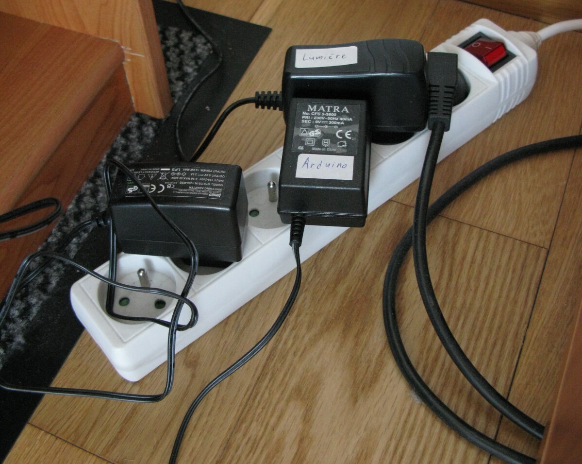
Arduino powering
The Arduino does not consume a lot of power. A 9V power supply of at least 300mA will do the trick. For information, the Arduino's mains connection has a 5.50 mm / 2.10 mm female socket.
Servomotors powering
The rewind servomotor that I recommend consumes a maximum of 640 mA while the scrolling one consumes a maximum of 1200 mA (see the datasheets in the links provided in the table at the top of the page). Both require a voltage of 6 V. Therefore, you need a power supply of 6 V that delivers at least 2 A.
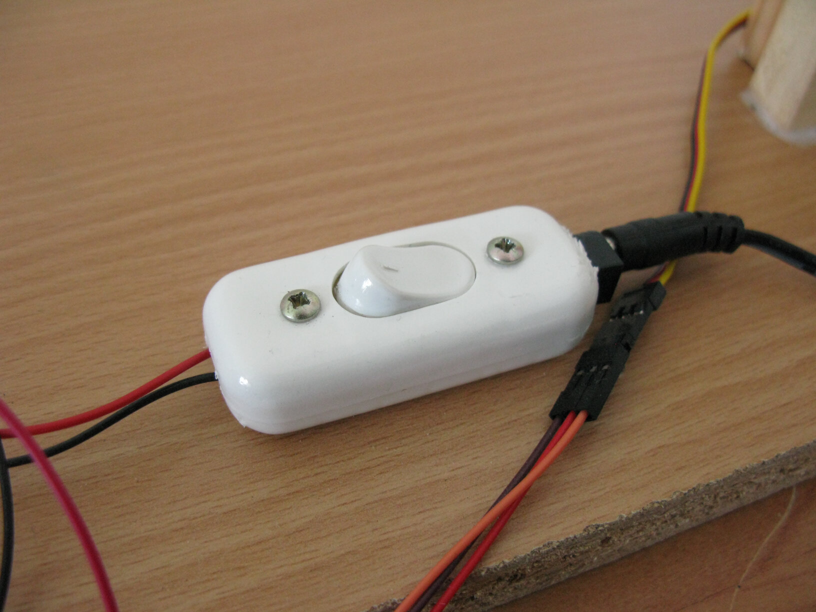
In order to avoid having to turn everything off when you want to stop the rotation of the servomotors, which can happen quite often if the perforations of the film are damaged, I recommend dedicating a switch to the servos on which you will graft a low voltage connector with a 5.50 mm 2.10 mm female socket. This is a simple, convenient and elegant way to hook them up to their power supply unit without having to butcher the latter (which I don't recommend). Additionally, if you turn off the power to the power strip while the servomotors are spinning, the servomotors will continue to run for a second before stopping as they will eventually dissipate the energy stored in the power supply unit. Turning off their power at this switch allows them to stop dead and independently of the rest of the system, which is extremely useful when you want to stop the scrolling precisely on a frame to adjust focus, exposure, etc.
To graft the low voltage connector, you will have to cut the switch so that it protrudes. The best thing to do is to screw the connector (which has two holes provided for this purpose) on the switch housing. In the photos, you will see that I chose a small switch. You can also try this choice, but note that I had a lot of trouble getting the connector into it.
LED powering
Beware because the connection of the Godox LED panel has a 5.5 mm / 2.5 mm female socket, while most power supplies available on the market have a 5.50 mm / 2.10 mm male connector (at least in France).
You need a 5 V block capable of delivering a minimum power of 5 W, with 5.5 mm / 2.5 mm connector.
To connect everything
Finally, you will need a power strip with 6 sockets to be able to connect everything to the mains. A model with a switch is essential to turn everything off at once.
By the way, I recommend plugging the camera into an independent outlet because sometimes you will need to let it on when everything else is off.
How to use it
That's it, the machine is assembled. Now you have to make it work properly.
Before first use
Calibrate the angle of the scrolling servomotor: ensure that the triggering of the shutter takes place at the right time by trying several positions between the servo horn and the white end of the servomotor. I recommend that you draw a mark on these two elements to easily find the right position later.
Set your camera to silent shooting mode and turn off all automatic functions. Set the white balance using the LED panel as reference, without film but with the diffuser, setting exposure so that the light is slightly gray rather than white.
Common use
Please excuse the few filming errors in the video.
Once the digitization is complete, all you have to do is edit your film. For this, I highly recommend DaVinci Resolve which is a professional and free software. It also allows perfect image stabilization options that I will perhaps develop in a future tutorial.
To clean the microfiber cloths, use lukewarm water and Marseille soap. Rinse well.
Problems and how to solve them
If the film does not rewind correctly and falls off the spool, here is an example of what can be done:
If the IR sensor causes problems, try changing its position. Otherwise, display the measured values on a computer via the Arduino interface. Change the limit value or disconnect / reconnect each pin.
If the camera has taken significantly fewer pictures than displayed on the LCD screen, the memory card is full or the camera is overheating. Change the memory card or take more frequent or longer breaks. If your device has an articulated (swivel) screen, open it to better dissipate the heat from the case.
If the film moves a lot between shots and the image is not stable at all after you edit the film, there may be an alignment issue. Play around with the orientation of the scrolling mechanism.
If the LCD screen keeps showing gibberish, there is a problem with the wiring. If, on the other hand, the phenomenon occurs completely randomly (this often happens when the system is stopped to readjust the focus), just stop the servomotors by opening their switch, wait 3 seconds and resume their rotation. Repeat until the display returns to normal.
What about the other film formats?
This guide is dedicated to a scanner for 16mm film format. But one could quite imagine adapting it to scan 8mm, Super 8 or 9.5mm film. In fact, the manufacturing is specially designed for this. The parts that are exclusive to a film format are all removable.
To be honest, I have even already adapted the system so that it is compatible with 8mm films. For this, I used the mechanism of a Bolex C8 camera (not expensive and the mechanism is ideal). I also created suitable pieces.
However, I did not find suitable 9.5mm or Super 8 mechanisms. I managed to scan a Super 8 film with the mechanism of the Bolex C8 by shifting it slightly. However, since the distance between the perforations is not the same, the claw rubs against the edge of the perforation when going up. Therefore, I don't guarantee it will work with all Super 8 films. It may be possible to tweak this mechanism further to make it work for Super 8 but I haven't tried it yet.
You may also want to consider investing in another lens that will further magnify the image because 8mm frames are much smaller than the ones of 16mm films. I recommend the LAOWA 25mm f/2.8 Ultra-Macro 2.5-5x.
Credits and links
To make this tutorial, I obviously did not start from scratch and here I want to cite my sources of information, which you can also consult if you want to obtain additional information.
The tutorial that served as a basis
I warmly thank Heikki Hietala, without whom nothing would have been possible: here.
Note that the servomotors used in this tutorial are very noisy. These are the ones I used with the early versions of the machine but I quickly replaced them.
Links
Film conservation recommendations: cine-super8.net
Another site on film conservation: psap.library.illinois.edu
Illustrations
Illustration of the Arduino Uno by PhilippHenkel
Licence
This tutorial is under Licence Creative Commons BY SA NC